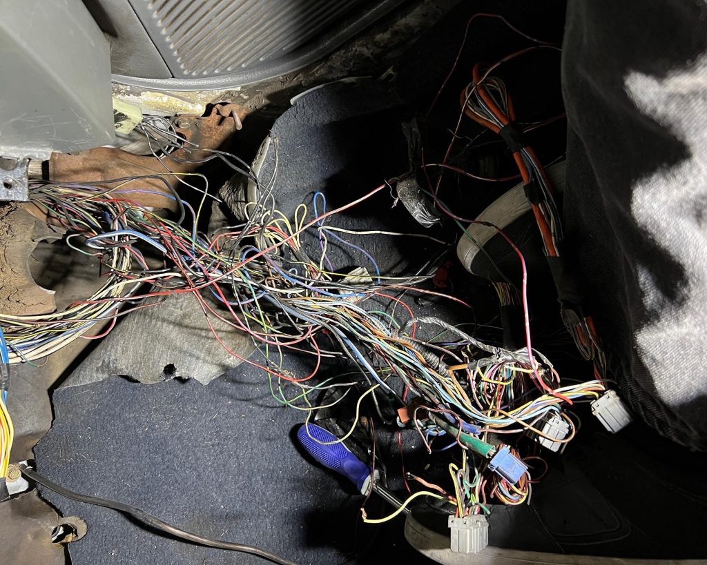
When I got the EH2 affectionately called “Junk”, it was in pretty bad condition in a lot of ways, but the wiring was probably the worst. The entire headlight/blinker harness was almost entirely missing, and the main harness had the original ECU connectors cut off and mangled. There wasn’t a lot of hope of fixing it and using the conversion harness in the process.
It’s worth noting this car was never expected to have much in terms of creature comforts, but even so, these cars are extremely easy to work with. The engine is 90% of it, and that was already being taken care of with the new K20 harness, ECU, and conversion harness I had already bought. There were only a few ‘gotchas’.
The conversion harness I used was specific to the 92-95 Honda Civic, but in retrospect, I would have opted for a Universal K Swap harness instead. The Hybrid Racing conversion harness supplies the OBD port, primary and secondary oxygen sensor connections, and the connection to the chassis harness in an almost plug and play method. There are a few connections you have to tap into specific places on the existing main harness, which is usually an easy task, but I couldn’t find, identify, or trust the wiring that was in the car. I couldn’t tell the difference between any of it. It was literally spaghetti wiring. A nightmare. So I ripped it all out and started over.
First thing I had to do was figure out what I wanted/needed to keep in terms of switches. For this car I wanted to retain as much of the street car features as possible. Keyed ignition, headlights, and blinkers. I am still waffling on the idea of keeping wipers for 2 reasons. First, the car is going to make somewhere between 400 and 500 horsepower when its done, and it doesn’t belong in any weather aside from clear and sunny, and second, I live in one of, if not the driest states in America. There is not a lot of reason to keep them. However, I will consider it once its a little further along.
The next step was to remove what was not needed. This mainly consisted of HVAC, power doors, power mirrors, stock radio wiring, and all of the damaged harness. This meant taking out the cluster wiring, main relay, and both fuse boxes. From here we were able to make a wish list, and start collecting pigtails. In order to salvage what I already spent money on, I started by trying to figure out what the conversion harness was doing. This starts with the Honda K20A2 harness C101 connector.
K20A2 C101
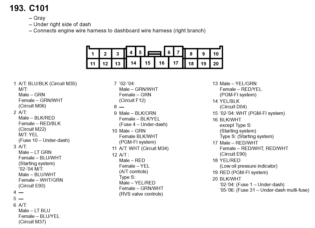
As you can see, this list lacks detail. This is found in many places on the internet. However, by tracing how the Hybrid Racing Conversion harness routes to the C302 on the Civic, I was able to identify what each pin did. Now that I know what I need to supply the conversion harness, I now need to source the rest and understand how the ECU works.
Civic C302
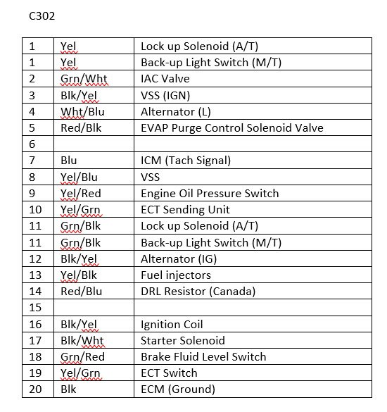
This is the Grey body connector the Hybrid Racing Conversion harness is supposed to plug into. This was a major key in understanding how to wire the car. The harness used is a 2002-04 Acura RSX Type S harness, and the C101 pins out differently than the Hybrid Harness. This helped a ton in understanding what the C101 connections were.
Once I had the key pieces of understanding, I had to make pigtails and a fuse box since I no longer used any of the OEM main harness. I cut off the Civic’s C302 and all the pigtails for the dash, blinker stalk, ignition switch and had to source some headlight connectors since mine were missing. I cut the connection to the rear taillight harness, and removed the defroster and other unneeded wires to the rear by depinning them. I kept the OEM connector behind the USDM driver to the rear harness.
C101 to C302
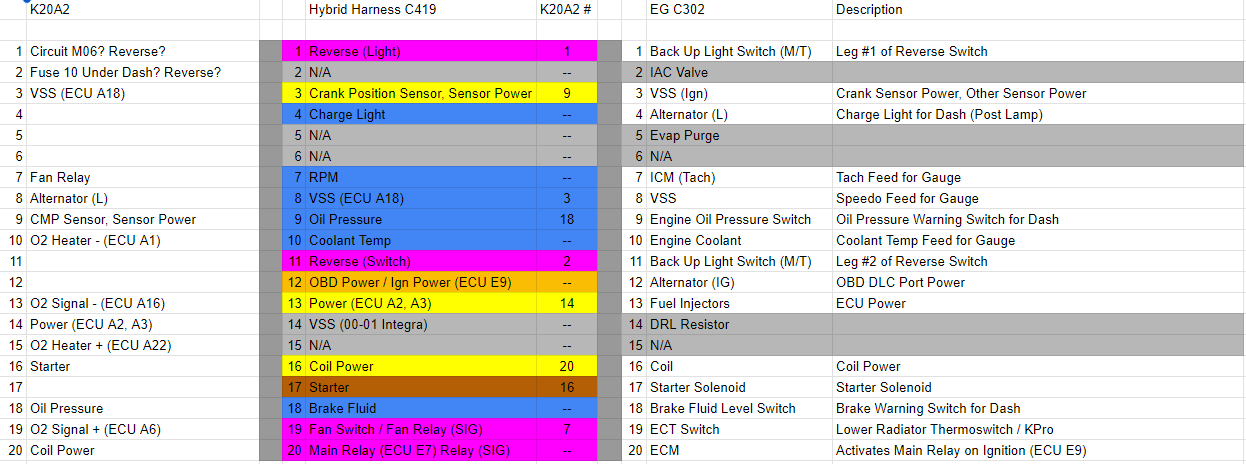
Next, I had to replicate the power to the C101 pins from the C302. This took some time to try and figure out. Take the Coil Power for example. On the K20A2 harness C101 connector, its pin 20. The Hybrid Racing conversion harness then routes it to pin 16 on the C302 connector. The reason why this took some time is because I had to verify both the C101 and C302 ends before moving forward. The only thing I could do was follow the changes.
Pink are signal wires, Orange is run/start power (key position 2/3), Yellow is main relay controlled power (controlled by ECU when key is in position 2/3), Brown is start power (key position 3). Blue are outputs (VSS, RPM), or ECU controlled lights (Charging Light, Brake Fluid, Oil Pressure, etc) from the ECU. A lot of the key positions were guessing based on when they were needed in the ECU sequence (See below). For example, crank position sensor power probably isn’t needed on accessory.
DIY Fuse Box
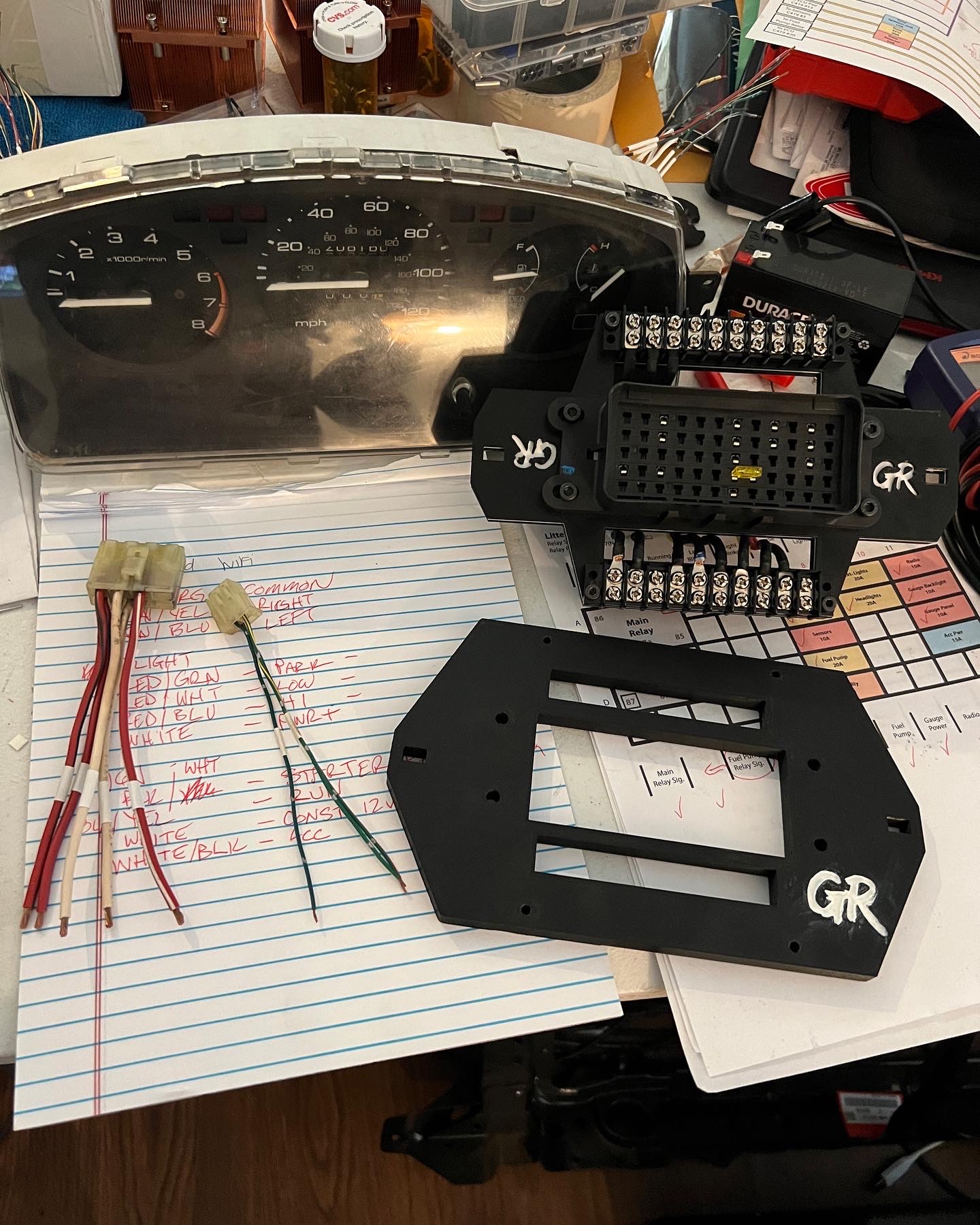
Since I was starting over, I figured using the existing fuse box was out of the picture. I did some looking around and found 2 options. Littelfuse HWB60, and Eaton Bussman Power Distribution Modules. Some companies like Rywire and Wiring Specialties even use these I believe. Both of these are really affordable and have some configuration options. Some of Bussman’s models even have internal power rails for less headache. I opted for the Littelfuse HWB60 for its compact size, and lack of rails, as I wanted 100% control over the wiring. I just needed the box.
I started with buying the following:
- Littelfuse HWB60
- Delphi 240 Series Connectors and Seals
- Wirebarn 12 Gauge Wires
- 4 Micro 240 Relays
- A Ton of Mini ATM Fuses
Waytek was a massive resource for this. I ended up buying almost all my fuse box parts from there. Once I had the box, the crimps and seals, and pigtails, the rest was easy. A major cheat code for the relays is knowing that some GM models in the mid-2000’s use Micro 240, so scoring some Tyco or higher grade relays is super easy. Some of the Song Chuan relays came DOA, so sourcing some better relays is highly recommended. I put some terminal strips on the frame as well so I could quick diagnose using a power probe, but this probably isn’t necessary. I did end up using some terminal bridges to get output from the main relay to the required circuits, and it was kind of messy in my opinion.
At this point, all I needed to do was to setup a fuse for everything I needed, as well as a couple relays. In order to do this, you have to dig in to the sequence of events the ECU goes through to be able to run.
ECU Process
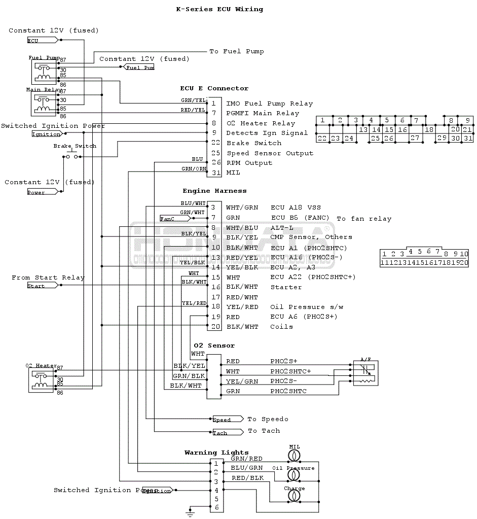
To get the wiring correct, we have to examine the steps the ECU takes to get to successful ignition. Hondata comes in clutch with the schematic that covers the basic operations of a K Swap, and it all starts with the Switched Ignition Power.
When the keyed ignition power is activated, power is given to Pin E9. This turns on the ECU and puts it in control. Per the diagram it also activates the oxygen sensor heater relay, but we are using the conversion harness that handles the oxygen sensor stuff, so we can ignore that.
Once the ECU has determined its ready, it activates the PGMFI “ground” (Pin E7) to the Main Relay. When the Main Relay is activated, power is passed to:
- Fuel Pump Relay (Not enabled, just gives it power for when the ECU activates later in the cycle)
- Crank Position Sensors \ Sensor Power
- ECU Power
- Coil Power
Now, this does not mean they are necessarily active at this time, but that power has been activated on them, and can be triggered successfully when the ECU wants it to. Now the above diagram works great, but we have an adapter harness. So we have to use the correct pins on our C302 connector to make sure we hit the right pins per the Hondata sheet, which is referencing the C101 on the K Series harness.
This translation makes the following happen for my conversion harness:
- C101 Pin 9 (Crank Position Sensor \ Sensor Power) -> C302 Pin 3
- C101 Pin 14 (ECU Power) -> C302 Pin 13
- C101 Pin 20 (Coil Power) -> C302 Pin 16
At this point, the ECU should be online at key on providing you give the right ignition signal to the ECU. It should stay on while cranking. If it drops, the ECU will not fire the engine.
After this, the ECU will activate the IMO Fuel Pump Relay (Pin E1). This should activate your fuel pump. Note that the switched side of the relay is wired to constant 12 volts, and then routed directly to the pump.
If these conditions are met, the engine should run. I successfully did this myself, and only had a single issue with starting because I used the wrong ignition switch wire from the EG chassis. Whoops. Afterwards, the car started beautifully and ran for a few seconds before I shut it down due to no cooling system. Its worth noting that if you have aftermarket injectors, you need to enter the scaling data, as well as disable any immobilizer stuff in Hondata to get it to start. I started with just a base map, and made the injector tweaks, then uploaded it to the ECU.
If you are running turbo, disconnect the charge pipes to get your first start. If you do not have things working properly, it could add to the frustration. Get it running first, then talk to your tuner when you are almost done and ready to get the car tuned.
Dash Lights
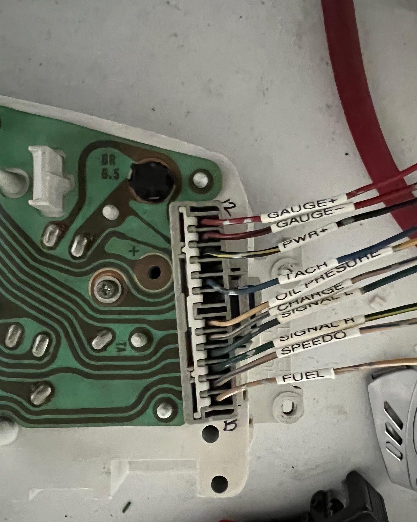
The dash lights are just as easy as well. There is accessory power to the cluster which is shared between multiple bulbs (PWR +). The wires for each light are wired to their corresponding pins on the harness. These are technically the grounds for the bulbs. The ECU will ground out the bulbs when necessary. This is for on or off signals only. Things like Check Engine, Oil Pressure, Charge, Signals, etc.
Tach, Speedo and Fuel are simple too. Tach goes to Pin 7 on C302 (Pin E26 on ECU), Speedo goes to VSS on Pin 8 on C302 (Pin 3 on C101), Fuel is directly to the sending unit in the rear harness.
Temperature has 2 modes of operation, one requires the D series coolant sensor to be installed in the K20 upper coolant housing (or somewhere where it can read reliably) or KPro can do this if you have that. Hybrid Racing’s conversion harness has more instructions on this.
The brake light needs to be wired to the master cylinder reservoir, but I have yet to do this yet.
That’s basically it. I’ll link the mass of documentation I used to help me get to this point below, but in reality, the Hondata schematic is probably the best. It helps decrypt the process more than anything, but the rest helps put that into physical terms.
The rest is just body wiring. Blinkers, brake lights, etc, and there isn’t much science to that. From here, you should have a ripping K Swap.
Happy Swapping!